Thanks for replying, I'm glad I did not cut it yet, I'll have to appeal and ask for help for
@arzi84 and see if he can tell me if that's where I should break the trail:
View attachment 104104
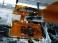
I compared the two boards (mine and tutorial) and realized the last pin (where we welded the wire) of the board of the tutorial has a track (where we should make the cut of this track):
View attachment 104106
My board does not have this track, only on the penultimate pin (one after where the wire should be welded).
With that I'm thinking: I should solder the wire in this penultimate pin (which has the track) and cut this track or my card has no way to follow this tutorial?